By Drew Cutchins - 17 October 2018
Inverse Kinematics is the practice of aligning a set of bones and joints to place their endpoint at a target position.
Inverse Kinematics has two common applications: animations in games and movies, and robotics.
We will be doing all of our calculations and examples in 2D but the formulas can easily be applied to three dimensions.
Let’s first create a way to define a collection of bones and joints:
class Armature{
    constructor(bones, joints, root){
        this.bones = bones;
        this.joints = joints;
        this.root = root;
    }
}

class Bone{
    constructor(length){
        this.length = length;
        this.endpoint = {x: 0, y: 0};
    }
}

class Joint{
    constructor(){
        this.angle = 0;
    }
}
Before exploring inverse kinematics, we should first explain it’s inverse, forward kinematics.
Forward kinematics is the calculation of an endpoint given the angles of joints and the lengths of bones. Given a list of bone endpoints, $P$, bone lengths, $L$, and a list of joint angles, $A$, the endpoint of a bone can be calculated as:
\[P_i = P_{i-1} + L_icos(\sum_{j=0}^i A_j){\hat{\textbf{i}}} + L_isin(\sum_{j=0}^i A_j){\hat{\textbf{j}}}\]Admittedly, this formula is a bit messy, so lets break it down a bit.
The first value, $P_{i-1}$, represents the endpoint of the bone to which this bone is attached. It makes sense that we need to first calculate this value, as the position of an endpoint is simply the previous endpoint plus the offset of the bone. The recursive nature of this formula means that whenever the length of a bone or angle of a joint is changed, all of the bone positions following the changed feature must be recalculated.
The second part of the formula multiplies the length of the bone times the sine and cosine of the summation of the angles leading up to the calculated endpoint. Note that we cannot simply use the angle of the most recent joint, as it is the angle relative to the most recent bone. By summating the leading angles, we can find the global rotation of the bone.
Lets create a function for calculating the positions of bones in an armature. This function should be called whenever the length of a bone or angle of a joint is changed. To make sure of this, we will also be creating functions for changing values pertaining to the bones and joints. Adjusting this values through direct access to the bones and joints arrays will not cause the endpoints of the bones to be adjusted and therefore should not be done from outside the class (unfortunately javascript does not supoort private instance variables).
class Armature{
    constructor(bones, joints, root){
        this.bones = bones;
        this.joints = joints;
        this.root = root;
    }

    adjustBoneLength(boneIndex, newValue){
        this.bones[boneIndex].length = newValue;
        this.recalculateEndpoints();
    }

    adjustJointAngle(angleIndex, newValue){
        this.joints[angleIndex] = newValue;
        this.recalculateEndpoints();
    }

    recalculateEndpoints(){
        var lastPosition = {x: this.root.x, y: this.root.y};
        var lastAngle = 0;
        for(var i = 0; i < this.bones.length; i++){
            this.bones[i].endpoint.x = lastPosition.x +
                this.bones[i].length * Math.cos(lastAngle + this.joints[i].angle);

            this.bones[i].endpoint.y = lastPosition.y +
                this.bones[i].length * Math.sin(lastAngle + this.joints[i].angle);

            lastAngle += this.joints[i].angle;
            lastPosition.x = this.bones[i].endpoint.x;
            lastPosition.y = this.bones[i].endpoint.y;
        }
    }

}
Now using some simple controls, try to get the end of the armature into the target circle.
First Angle:
Second Angle:
Third Angle:
Not too hard right? But how would you tell a computer to do that?
It would be easy if we only had a couple of joints, we could use some simple trigonometry.
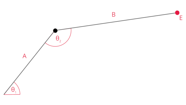
Given the above armature with endpoint E, the two joint angles are fairly trivial (though rather messy) to compute using the law of sine and law of cosine:
\[\theta_2 = 180 - cos^{-1}\frac{E_x^2 + E_y^2 - A^2 - B^2}{2AB}\] \[\theta_1 = tan^{-1}\frac{E_y}{E_x} - tan^{-1}\frac{Bsin{\theta_2}}{A + Bcos{\theta_2}}\]I will spare you the algebra, but if you are curious this video works out the solutions.
However, as we continue to add more joints, it becomes harder to find an analytical solution. More importantly, whenever the number of degrees of freedom of the armature becomes unequal to the number of joints it becomes impossible to algebriacally find a solution (This will happen as soon as we bring our armature into three dimensions). This is where the multiple methods of inverse kinematics come into play.
In this article, I will be explaining the method known as cyclic coordinate descent (CCD). There are other strategies such as the jacobian inverse method, that I may explore in later posts.
In CCD, each joint of the armature is iterated, and brought to an angle that brings the endpoint of the armature closer to the target position. This iteration is repeated until the distance between the endpoint and the target position falls below a specified threshold.
The amount the angle of a joint should be changed will be the angle between the vector pointing from the position of the joint to the end of the armature, $\vec e$, and the vector between the position of the joint to the target position, $\vec t$. The formula to find this angle, $a$, can be calculated as:
\[a = \frac{cos^{-1}(\vec t \cdot \vec e)}{\lvert e\rvert \lvert t\rvert}\]This is simply the inverse cosine of the dot product of the two vectors, divided by the product of the magnitudes of the two vectors. This formula relies on a property of a dot product (the summation of the products of the corresponding dimensional values of a vector) which states that:
\[\lvert a\rvert \lvert b\rvert cos(\theta) = \vec a \cdot \vec b\]With this formula is mind it is rather simple to create our inverse kinematics functionality.
class Armature{
    // ...

    applyInverseKinematics(targetPosition){
        while(distance(this.bones[this.bones.length - 1].endpoint, targetPosition) > 1){
            this.approachTarget(targetPosition);
        }
    }

    approachTarget(targetPosition){
        for(var i = this.joints.length - 1; i >= 0; i--){
            // e
            var jointToEndpoint = {
                x: this.bones[this.bones.length - 1].endpoint.x - this.bones[i].endpoint.x,
                y: this.bones[this.bones.length - 1].endpoint.y - this.bones[i].endpoint.y
            }

            // t
            var jointToTarget = {
                x: targetPosition.x - this.bones[i].endpoint.x,
                y: targetPosition.y - this.bones[i].endpoint.y
            }

            // e * t
            var dotProduct = jointToEndpoint.x * jointToTarget.x +
                jointToEndpoint.y * jointToTarget.y;

            // |e||t|    *note that mag is a function defined elsewhere
            var magnitudesProduct = mag(e) * mag(t);

            // arccos(e * t)/(|e||t|)
            this.joints[i].angle = Math.acos(dotProduct) / magnitudesProduct;

            this.recalculateEndpoints();
        }
    }
}
Test out the following example that has the arm follow the mouse! Use the sliders to change the lengths of different bones.
First Bone:
Second Bone:
Third Bone:
Fourth Bone:
With our IK system set up, we can continue to add features to create interesting behavior.
First lets add some contraints to our joints, such as a minimum and maximum angle.
class Joint{
    constructor(minAngle, maxAngle){
        this.angle = 0;
        this.minAngle = minAngle;
        this.maxAngle = maxAngle;
    }
    set Angle(newAngle){
        if(newAngle > this.maxAngle){
            this.angle = this.maxAngle
        }
        else if(newAngle < this.minAngle){
            this.angle = this.minAngle;
        }
        else{
            this.angle = newAngle;
        }
    }

    get Angle{
        return this.angle;
    }
}
Now all we have to do is replace all of our references to “angle” in the armature class with our new property “Angle” (note the change in case).
In the following example, I’ve contrained the range of motion of all of the joints to 45 degrees, note the change in behavior from our previous example.
This armature behaves far more organically, resembling the behavoir of a tentacle. As you may have noticed, while playing with the above example, it is possible to make the armature lock in place, unable to approach the target. To replicate this flaw, bring your mouse to the upper right hand corner of the display, then try to form the armature into an S shape. After doing so, bring your mouse towards the bottom left hand corner of the display. This should “lock” the armature, causing it to fail to meet a target it could otherwise reach. This behavior is a shortcoming of the CCD algorithm that is solved in some of the other IK implementations.
I hope you enjoyed this article, and that you’ve learned something new! Feel free to leave any questions or comments below.